Part 6 · Control Loops
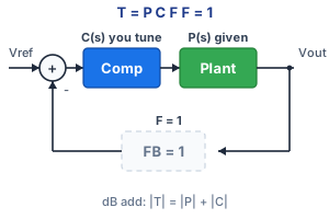
Key point: the plant is given. You do not redesign it — you add \(C\) on top. With \(F=1\), dB add: \(|T|=|P|+|C|\). Slide \(C\) until purple \(|T|\) crosses 0 dB at the gold target \(f_c\), with the phase margin you want.
Target \(f_c\) and PM — plant stays put, you tune C
Given plant — not the exercise
T = P · C. Raise C gain to walk fc. Place the zero below fc to buy phase margin.
Output bump · loop pulls Vout back to 0
Parts · |P| given + |C| you tune · drag handles
Loop gain T = P · C
A one-pole plant plus a number \(K\) already has PM ≥ 90°. That is too easy, and it has finite DC loop gain. Power stages need the extra pole at the origin so leftover DC error goes to zero. Then at high \(f_c\) you have roughly −90° from \(C\) and −90° from \(P\): PM sits near 0°. The zero buys some of that back:
\[ C(s)=G\Bigl(1+\frac{\omega_z}{s}\Bigr) \qquad \mathrm{PM}=180°-\arctan(f_c/f_p)-\arctan(f_z/f_c) \]\(G\) (the C-gain slider) sets how high \(|C|\) sits after the zero — that walks \(f_c\). \(f_z\) sets how much phase is back by crossover. A Type II network (later) adds a high-frequency pole so \(|C|\) does not stay flat forever. A real \(F\) (next lesson) is another dB and phase term in the same sum.
A \(V_{\mathrm{ref}}\) step of this PI would overshoot more than the PM rule of thumb: the zero is in the reference path. The lab’s time plot is an output bump instead, so leftover ringing tracks the closed-loop poles (the PM you bought) without that extra kick.