Loop Filter Parameters
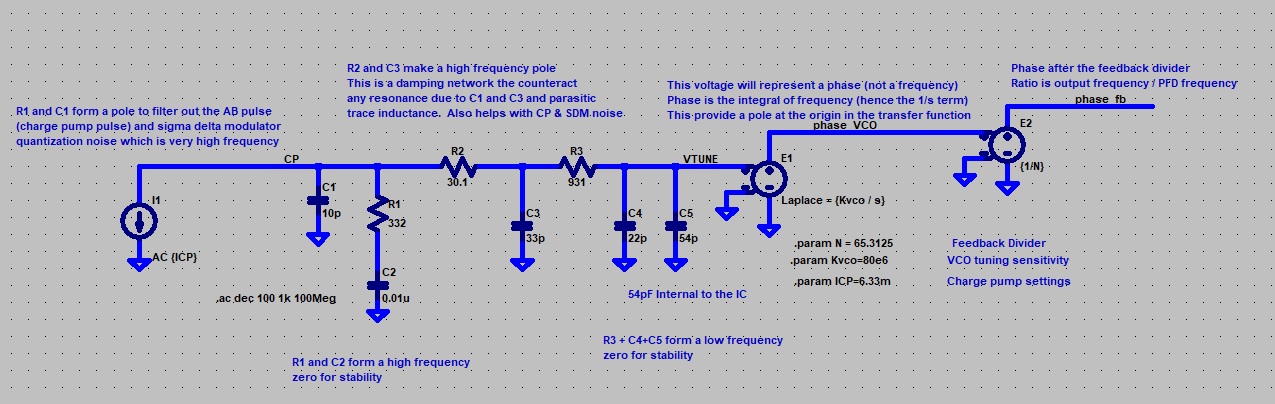
High-freq pole approx: \( f_{p1} = \frac{1}{2\pi R_1 C_1} \)
Zero: \( f_z = \frac{1}{2\pi R_1 C_2} \)
Zero: \( f_z = \frac{1}{2\pi R_1 C_2} \)
Damping, high-freq pole approx: \( f_{p2} = \frac{1}{2\pi R_2 C_3} \)
High-freq pole approx: \( f_{p2} = \frac{1}{2\pi R_2 C_3} \)
High-freq pole approx: \( f_{p3} = \frac{1}{2\pi R_3 (C_4 + C_5)} \)
High-freq pole approx: \( f_{p3} = \frac{1}{2\pi R_3 (C_4 + C_5)} \)
Fixed internal VTUNE capacitance, typical 54 pF
High-freq pole approx: \( f_{p3} = \frac{1}{2\pi R_3 (C_4 + C_5)} \)
Typical range: 50–150 MHz/V
Open-Loop Gain
X: - kHz, Y: - dB
Open-Loop Gain G(s): \( G(s) = \)
DC Impedance: - (Low-freq gain normalized)
Loop Bandwidth: - kHz
Phase Margin: - °
Zero (R1·C2): -
Pole 1 (R1·C1): -
Pole 2 (R2·C3): -
Pole 3 (R3·(C4+C5)): -