Analog Intuition

Part 2 · Voltage Regulation

Why a resistor divider fails

Key point: dropping 12 V to 3.3 V with a series resistor can hit the voltage at one current — but load steps and efficiency kill it. A bulk cap only slows the failure.

Series dropper · load step

12 V → \(R\) → 3.3 V · 10 µF · profile 100 → \(100{+}\Delta I\) → 100 → \(100{-}\Delta I\) · dwell ~6τ

\(V_{\mathrm{OUT}}\) · blue in-spec · red out · green = ±5% around 3.3 V

\(I_{\mathrm{LOAD}}\) · 100 mA → up → 100 mA → down

Status
\(R_{\mathrm{series}}\)
V plateaus (4)
\(\tau = RC\)
\(P_{\mathrm{load}}\) @ 100 mA
\(P_R\) @ 100 mA
\[ R = \dfrac{V_{\mathrm{IN}}-V_{\mathrm{nom}}}{I_0} \]
\[ V_{\mathrm{ss}}(I) = V_{\mathrm{IN}} - I\,R \]
\[ P_{\mathrm{load}} = V_{\mathrm{nom}} I_0,\quad P_R = (V_{\mathrm{IN}}-V_{\mathrm{nom}}) I_0 \]

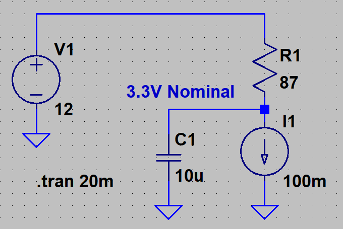
Circuit: stiff \(V_{\mathrm{IN}}\) → series \(R\) → node with current load + \(C\). After a current step, \(V\) exp-settles with \(\tau = RC\) toward \(V_{\mathrm{IN}}-IR\). Trace is red while outside ±5%.

Try it: default ΔI = 10 mA → sequence 100·110·100·90 mA. Watch a clean blue start at 3.3 V, then slow red excursions as \(V\) crawls with \(\tau=RC\). ΔI = 0 stays flat in-band — still dumps most power in \(R\).

References

  1. Basso, Christophe P. Switch-Mode Power Supplies: SPICE Simulations and Practical Designs. New York: McGraw-Hill, 2008. (See the discussion of converting power with resistors — series dropper at one design current.)